~ Why correct configuration is key to maximising the value of VSDs ~
Variable speed drives (VSDs) have become a staple across industrial and agricultural sites. But while these devices are increasingly being fitted, their full capabilities are often overlooked. Here, David Strain, technical director at automated systems specialist Technidrive, explores the world of untapped possibilities waiting within every inverter that can unlock performance, control and energy efficiency — provided they are set up correctly.
For many operations, adding a VSD is the first step in a wider journey toward automation, efficiency and improved control. A VSD regulates the speed and torque of a motor to match the exact demands of the process, rather than running at full power constantly. However, in our experience, the benefits of that first step are often under-appreciated.
When properly set up, an inverter doesn’t just provide speed control for an electric motor — it also enables fine-tuned management of current, torque, power factor and ramp-up profiles. The result? Better motor performance, lower startup currents and reduced wear and tear on equipment. But if your VSD is left running out-of-the-box parameters, those benefits can be lost.
Let’s take a closer look at what a good setup looks like — and what can happen when this is overlooked.
Getting the basics right
Most VSDs are pre-configured for Variable Frequency (V/F) control, which suits variable torque loads like fans and pumps — applications where less torque is needed as speed decreases. However, this setup isn’t suitable for constant torque loads such as conveyors or elevators, where the weight of the material stays the same regardless of speed.
In these cases, the motor still needs to deliver full torque even at low speeds. If V/F control is used in these situations, the drive reduces voltage along with frequency, which limits the torque available. This can lead to stalling and inefficient performance when the motor is under heavy load but running slowly.
Instead, the key is to use “sensorless vector control”, or “sensorless flux vector” mode. This is a form of open loop control that enables high torque production even at low speeds, without needing additional encoder hardware. When configured correctly, it gives operators full torque from 5 Hz upwards, ideal for demanding applications like feeders, crushers or conveyors under heavy load.
Example: Feeder control in agriculture
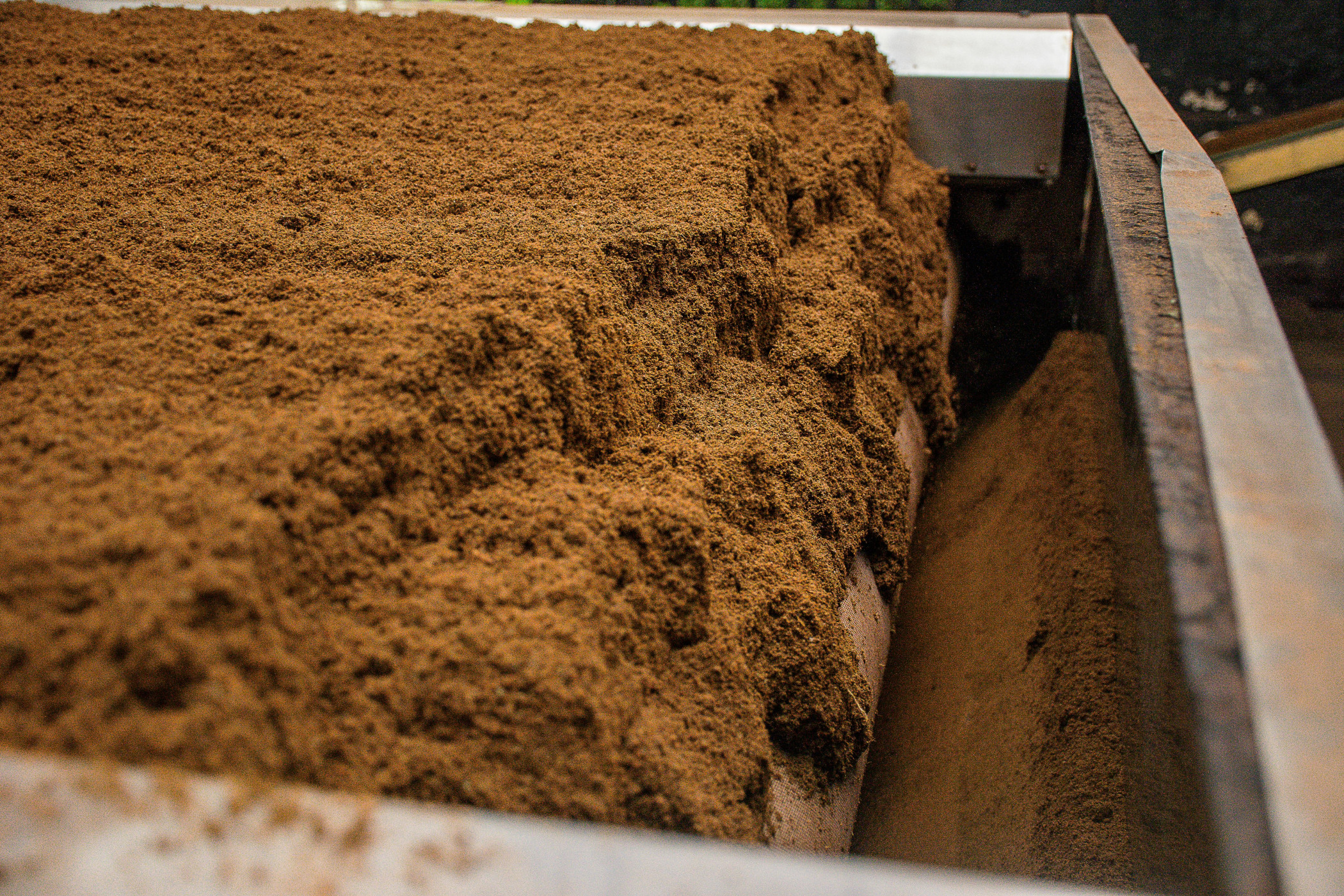
One good example of the value of a correct setup is Technidrive’s work with Kerry Agribusiness at its feed mill in Farranfore, County Kerry, Ireland.
The mill’s feeding system, which delivers raw materials into the grinders, previously relied on manual speed adjustments. Operators used experience and trial and error to find the right settings — a method that often led to inefficiencies. When speeds were too low, throughput dropped. When too high, the material wasn’t milled properly, affecting quality.
Technidrive replaced this with an automated feeder control system using a WEG CFW11 frequency inverter. Configured in sensorless vector control with a tailored feedback loop, the system automatically adjusted the feeder speed based on real-time conditions. The result was a 29 per cent increase in throughput and significantly reduced manual adjustments.
A properly set up inverter can unlock untapped potential in industrial conveyors, and other applications when current, torque and power factor present challenges.
Common mistakes — and how to avoid them
A common mistake is using the wrong control mode for the load. For example, a conveyor left in default V/F mode can lose torque at lower speeds and risk stalling — a serious issue in feeders running under constant load.
Another pitfall is assuming slower always means more efficient. While speed reduction can save energy, this only works if the load is monitored and the system properly adjusted.
A better approach is to use the VSD’s current sensing capability to dynamically adjust speed. If the belt is under-loaded, speed can be reduced; if it’s heavily loaded, speed can increase — always aiming for optimal utilisation.
In some projects, Technidrive has used Proportional–Integral–Derivative (PID) loops to adjust motor speed based on load feedback from the VSD itself. No extra sensors or hardware are involved — just smarter use of existing data for better control and efficiency.
As inverter technology evolves, so does the scope of what’s possible. Modern models like the WEG CFW900 now include integrated web interfaces. This opens possibilities for data-driven maintenance, optimisation and energy management — all without adding new hardware.
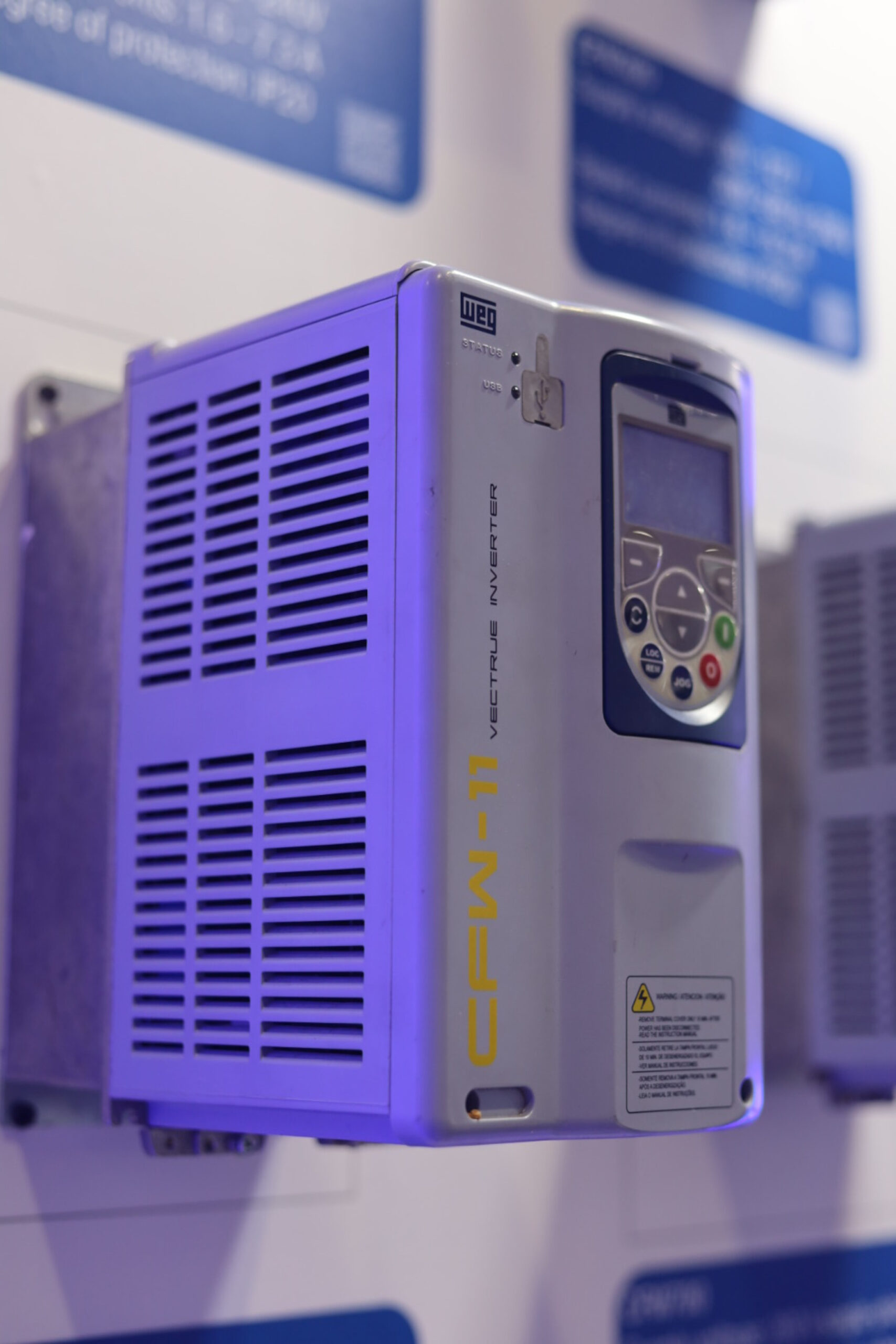
For Ireland’s Kerry Agribusiness, Technidrive helped implement an automated feeder control system using a WEG CFW11 frequency inverter.
Real-world value
Technidrive has seen countless examples where a smarter inverter setup has delivered results. In one case, a customer fitted a VSD purely to reduce startup current on a conveyor but didn’t realise it could also be used to control belt load and energy usage. Once we explained the potential, we helped them implement a load-based feedback loop using only the existing drive. Again, no extra sensors, just a better setup.
Demand for automation, performance and energy efficiency is on the rise — and inverters are key to delivering all three. A VSD running on default settings may work, but it won’t optimise your system. With the correct configuration, you can access smarter control, greater efficiency and a stronger return on investment (ROI) — and unlock that hidden potential within.
Not sure your frequency inverters are optimised? Small setup changes can deliver big gains — visit Technidrive’s website to learn more.